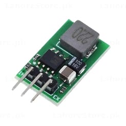
3-in-1 DC-DC Buck Converter Module Selectable 3.3V 5V 12V Fixed Output - Step-Down Power Supply
3-in-1 DC-DC Buck Converter Module Selectable 3.3V 5V 12V Fixed Output - Step-Down Power Supply
Regular price
Rs.160
Regular price
Sale price
Rs.160
Shipping calculated at checkout.
Quantity
Couldn't load pickup availability
3-in-1 DC-DC Buck Converter Module - Selectable 3.3V / 5V / 12V Fixed Output Step-Down Power Supply
A versatile step-down buck converter module with three selectable fixed output voltages. Simply solder the output selection jumper pad on the back of the board to set your required output - 3.3V, 5V, or 12V - and connect your power source. Ideal for powering microcontrollers, sensors, and modules in embedded projects where a fixed regulated voltage is needed without a multi-turn potentiometer.

Key Features
- 3 selectable fixed output voltages: 3.3V, 5V, or 12V - chosen by soldering the back-pad jumper
- Step-down (buck) topology - efficient DC-DC conversion, lower heat than linear regulators
- 3-pin through-hole output header - direct breadboard or PCB mount
- Compact green PCB - minimal footprint for tight enclosures and prototype boards
- Suitable for input voltages above the selected output (e.g. 7-24V input for 5V output)
- Onboard inductor and filtering capacitors - clean regulated output
- No adjustment needed after soldering - stable fixed output voltage

Specifications
- Topology: Step-Down (Buck)
- Output Voltage Options: 3.3V / 5V / 12V (solder-pad selectable)
- Input Voltage: Must exceed selected output (typical: 5V-24V DC)
- Output Selection: Solder jumper pad on back of PCB (3.3V / 5V / 12V)
- Output Connector: 3-pin through-hole header (IN, GND, OUT)
- PCB Color: Green
- Form Factor: Compact inline module

How to Select Output Voltage
- Inspect the back of the PCB - three solder pads are labeled 3.3V, 5V, and 12V
- Bridge the pad corresponding to your required output voltage with a small solder blob
- Apply input voltage above your selected output and verify output before connecting your load
Perfect For
- Arduino, ESP32, and Raspberry Pi Power Supply from 12V or 24V Sources
- 3.3V Sensor and Module Power Regulation
- 5V Logic Level Power in Automotive and Industrial Applications
- 12V Fixed Regulated Output from Higher Voltage Source
- Embedded System Power Rail Design and Prototyping
- Electronics Lab Bench and Breadboard Power Supply Module
Order now and get a compact, selectable fixed-voltage buck converter for your next embedded power supply project.